
I’ve been watching the Solder Smoke direct conversion receiver challenge build and thinking of maybe building it from parts I already have laying around… assuming I wind my own toroids. I haven’t noticed anyone talking about antenna stuff. What is the deal here?
This is the principal video series primer: https://www.youtube.com/watch?v=rLjxU2rMeXw
It is also on hackaday too.
Is there some rule about antenna where a more specialized element is required at specific frequencies? I know I’m missing fundamental practical information here as the wave length for 7 MHz is around 43 meters. Even a quarter wave length would involve a house spanning wire. So what gives, what high school fundamental have I forgotten?
The gist of it is that antenna length can be “faked”. Sure, it’s not as good as matching the wavelength (or a fraction thereof) with your antenna, but it is possible to have a shorter antenna and have parts of the length being an inductive (or capacitive? I forget…) load that makes up for the missing length.
Source: Used to do a lot if MF/HF installs on ships. Right before the actual antenna we use a Tuner, which is basically additional loads that helps matching the frequency. When transmitting on a new frequency, you key in the radio to let the tuner do its job, and then you rekey to do the actual talking. When the tuner is adjusting to the new frequency you can actually hear a series of relays clicking inside to connect the necessary loads.
What challenges are you facing? It’s a small mercy that antenna fundamentals are basically the same across all frequencies. The resonant element must be sufficiently long as to present an impedance match (or be brought down through via a transformer; 9:1, 49:1, or whichever flavor you need).
On 40m (~7Mhz) a dipole would need to be ~67’ long. You can get away with shorter, bearing in mind the compromises which come with that.
deleted by creator
What are the compact options short of a small wire and palm tree? I could probably etch that length on a couple of a4 size sheets of copper clad from ABC at around my minimum resolvable pitch size.
I’ve never really wrapped my head around impedance in this kind of context to the point of a functional fundamental understanding. I know the basic explanations and definitions well. It is like AC resistance; high impedance means low current potential, aka needs buffering or gain; low impedance is deadly microwave transformers and welding type stuff. I have wound my own I/E core transformers and built a dozen switching supplies, but I do not understand what you mean here by using impedance matching with a transformer. I would like to.
Great questions, one which highlights my own knowledge gap beyond knowing that for a given feedline and antenna combination, you’ll have some measure of impedance. At the most basic level, your radio will “see” some impedance value. In the amateur radio world this is generally 50Ω. If our antenna system (feedline + radiator) presents 450Ω (quite common), we use a 9:1 transformer to get it to match. This allows us to use our radio on that system without (1) stray current returning to the radio and damage our transmission circuits, and (2) at full power but with inherent loss of signal owing to antenna inefficiency.
Case in point, I have a commercially-purchased multi-band EFHW antenna which presents varying amounts of impedance to the radio. This system includes a transformer (I think it’s 9:1) so that on the bands of interest, there’s a resistance match and as a result an SWR that’s suitable to make decent transmissions on.
As a tangential example, J-pole antennas have a built-in matching system which uses no special parts. It’s composed of a matching section and radiator. The combination of matching section, radiator length, and physical feedpoint allow this type of antenna to sort of self-manage impedance.
The difference here is that a j-pole is a monoband antenna, and a long wire with transformer can often be functional on many bands, depending on length, where the lowest useable frequency is the inverse of its length.
So by using a transformer, I think you are essentially lowering the voltage to exchange for current. What I do not understand, assuming that simple assumed relationship is correct, is why it is still at thing people do. Like if we lived in the old days of vacuum tubes or bipolar junction transistors, sure it makes sense that a little more current might help. Now, in the era of rail to rail op amps with JFET inputs, I don’t understand why anyone needs to create the Eddy current losses of a transformer. Maybe it is safety from transients? But then why attenuate… and why not resistively for a more simple RLC element… very curious now…
There is certainly a lot to learn, and you would benefit greatly from joining the hobby officially. If you are US-based, you can take the amateur radio exam after memorizing the answers for the exam (a legal and encouraged practice), the exam itself can be administered remotely via Zoom.
I am beyond my technical knowledge if I tried to explain why we use transformers to get an impedance match; I only know what we do.
transformers are not the only way to do this, and some other circuits can be used instead. if you take a transformer with 1:2 winding ratio, then if on one side current is 1 and voltage is 1, then on the other current will be 0.5 and voltage 2, which means that impedance increases 4x. in EFHW, it’s 1:7 winding ratio and impedance ratio is 49x, which works for end-feeding a half-wave dipole, just as expected (from 50 ohm to ~2500 ohm). that transformer is a limitation on power usable in this antenna and main reason to use this type of antenna is mechanical
most importantly, transformers work nicely only if you have real impedances, so your antenna has to be resonant anyway. l- or pi-network tuner will also handle complex impedances so doublet or random wire will work nicely with it, as long as you can accept weight and losses in tuner
if you have an antenna with impedance of, say, 200 ohms, then you need to match it to transmitter impedance of 50 ohms, or else most of power output from transmitter would be bounced back and will damage output stage of amplifier. because on receive currents are tiny, you can wing it by just using it without any match and connecting it directly
how compact and what do you want to do with it? if it’s for receive only, the most compact you can get is ferrite rod antenna, but it’s very different from usual wire antennas used for transmission. if using wire antennas, random wire would be fine
it depends on whether you want to transmit or not. if not, you can just use random wire antenna
random wire antenna is exactly what it says on the tin - length of random wire strung up as high as you can, as long as you can make it work. the other part is ground, where you might want to lay some lengths of wire and connect them in a single point, to act as radio ground. it won’t have right impedance (probably 50 ohm) but for receive, this is ok - it’ll be probably usable, and you can amplify signal without penalty because amplifier noise will be much smaller than atmospheric noise already present. the amount of power bouncing around is tiny and can’t damage anything
if you want to transmit, you’ll need more elaborate antenna. what you can use depends on whether do you have a tuner like neidu3 describes or not. if you do, common choice is doublet which is a specific length of wire connected to tuner with a 400-ohm parallel line. if you don’t, common choice is halfwave dipole which is halfwave long, and put as high as you can get, either vertical or horizontal, but for practical reasons mostly horizontal, or monopole, that is quarterwave long, but requires lots of wire on ground to act as radio ground. you can make them shorter using coils, but this makes bandwidth narrower. in any case, it’ll be need to be tuned to your band in question, for which you need a tool like nanoVNA. tuner also narrows your bandwidth, but you can retune it so it doesn’t matter that much. (it’c called instantaneous bandwidth)
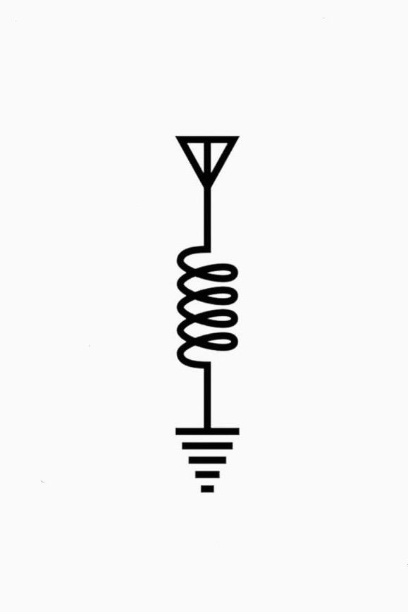
I would see about putting a big loading coil on the antenna when you make it. You would still need a really long wire, but you can at least make the overall antenna length shorter than you otherwise would be able to.